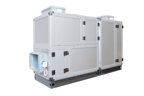
Modular duct device for the air treatment
At a Glance
Description
Technical data
Configuration
Planning and assembly instructions
- Duct device for the installation in the technical room - No disruptive devices in the swimming pool
- 5 sizes from 700 to 4000 m³/h
- Different air routing variants permitting a simple duct routing
- Thermally decoupled housing
- Extensive functional and equipment features
- Good indoor climate in the pool thanks to constant admixture of outside air
- Problem-free introduction thanks to the modular structure
- No cooling circuit - therefore easy to maintain and service
- Low energy consumption
- Simple heating connection through compact control station
- Broad range of accessories
- Coordinated air duct system
- Constant power adjustment by means of energy-saving, stepless EC direct current motors
- Additional savings and noise reduction through demand-dependent, stepless operation
- Better efficiency of energy recovery with reduced air volume
- Comparison between the supply and exhaust air volume can be carried out very precisely (vacuum setting)
Touch panel control equipped with a colour display of 4.3 inch
- Simple menu-driven operation
- Integrated web server
- Logging of alarms and any system data (actual values etc.)
- Comprehensive software options through simple configuration
- Switching between useful and eco mode through the internal timer or remote control
- Outside temperature dependent humidity shift
- Min. and max.limitation of the supply air temperature
- Various bus interfaces
Equipment list
The device consists of 2 housing parts
Part 1 (basic module)
equipped with supply air fan, exhaust air fan, mixed air chamber, PWW heating register, supply air filter, and control cabinet equipped with a control unit.
Part 2 (WRG module)
with heat exchanger for energy recovery, condensate collecting tray, droplet separator, exhaust air filter
Housing
Stable, corrosion-resistant profile frame construction made of aluminium hollow chamber profiles, powder-coated. The profiles are thermally decoupled by means of integrated plastic webs, so that the heat transfer between the device chambers and the environment can be reduced to a minimum level. Cladding panels equipped with highly insulating Hydrotec foam core. Circumferential base.
Supply/extract air fan
equipped with energy-saving, stepless EC direct current motors.
Mixing chamber
as an outside air/circulating air mixing chamber with two louvre flaps opening in opposite directions.
Air heater
Pull-out heat exchanger for hot water operation.
Supply air/extract air filter
Slide-in frame equipped with a Z line filter. Filter cell with pleated filter medium, fully incinerable and metal-free.
Energy recovery
Pull-out plate heat exchanger for the heat recovery of the sensible and latent heat energy contained in the air flows.
Coated stainless steel condensate pan equipped with a side drainage connector.
Control cabinet and control unit
integrated in the device with all modules for all tasks in the fields of control and monitoring.
Control package equipped with a touch panel control UNICON C, a colour display of 4.3 inch, and integrated in the control console.
Various interfaces (Ethernet TCP/IP, CAN, OPC, RS484, RS232) enable the connection to building management as well as third-party systems. Thanks to the optionally integrated web server, the operation or data transfer can take place through the internet as well. Various software options.
| Size | 0 | 1 | 2 | 3 | 4 |
|---|---|---|---|---|---|
| Nominal volume flow m3/h | 700 | 1250 | 2000 | 3200 | 4000 |
| Dehumidification performance (according to the standard VDI 2089) kg/h | 4.3 | 7.6 | 12.6 | 19.5 | 27.6 |
| Water surface, max. 1) m2 | - 28 | 25 - 40 | 45 - 80 | 60 - 125 | 80 - 150 |
| Total power consumption KW | 0.36 | 1.1 | 1.1 | 2.1 | 2.1 |
| Voltage V | 230 | 230 | 230 | 400 | 400 |
| Type | WRC-0 | WRC-1 | WRC-2 | WRC-3 | WRC-4 |
1) The exact calculation in accordance with the standard VDI 2089 is required
Device
5 sizes
12 design variants
Alternative equipment
- Connection piece for transition to ISO duct
- Connection piece (special size)
- Connection piece for transition to round duct
- External low-temperature PWW heating register control
- Conversion for the external installation of the control
- Duct humidity/temperature transmitter
- Duct humidity/temperature transmitter for rec. req.
- Air quality transmitter CO2 exhaust air sensor installed
- Air quality transmitter CO2 room sensor
Additional equipment
- Height-adjustable feet
- Conversion for the external installation of the control
- Comfort humidity shift
- Room/water temperature deviation control
- Volume flow control equipped with pressure transmitter
- Electronic filter monitoring with display of the pressure
- Activation of useful/ECO operation
- Control of additional heating
- Activation of the fire damper
- Activation of the BMA/smoke detector with feedback
- Smoke detector with VDS approval including control
- Forced shutdown by the furnace
- Activation of fault message condensate pump
- External activation Switching contact "forced ventilation"
- Additional switching output "forced ventilation" with overrun
- Interface RS485 OSPA, OSF
- Interface Ethernet OPC protocol
- Universal I/O interface (0..10V) + DE / DA
- Interface Ethernet Modbus-TCP protocol V1.0
- Interface RS 485 Modbus-RTU protocol V1.0
- Web server with integration in UNICON C
- VPN remote maintenance router including Cloud portal
- Interface KNX/EIB
- Interface Ethernet Sopra Cloud Portal
- Interface Ethernet Modbus-TCP protocol V2.0
- Interface RS 485 Modbus-RTU protocol V2.0
Accessories
- Compact control station
- Mounting kit for the external control, with wall mounting
- Mounting kit for the external control, with flush mounting
- CAN bus cable 2x2x0.25 mm²
- Remote control W-FBS standard
- Replacement filter (set)
General planning information
- Determination of the size (according to VDI 2089)
- Determination of the space requirements and of the appropriate installation site
- Check of the size of the insertion opening
- Provision of electrical feed to the device
- Provision of electrical cables from the device to the outside temperature sensor
- Electric cable from the device to the room humidity/temperature transmitter (not applicable to the option "Duct humidity/temperature transmitter")
- Provision of electrical cables from the device to the remote control (optional)
- Provision of a (flow and return) heating connection pipe to the device
- Provision of a condensate line from the device to the sewer
- Determination of the number, length, type and position of the supply air floor slot rails
- Determination of the line routing and dimensions for the supply air duct
- Determination of the number, size and position of the exhaust air grilles
- Determination of the line routing and dimensions for the exhaust air duct
- Determination of the position and size of the outside air opening
- Determination of the routing and dimensions for the outside air duct
- Determination of the position and size of the exhaust air opening
- Determination of the line routing and size of the exhaust air duct