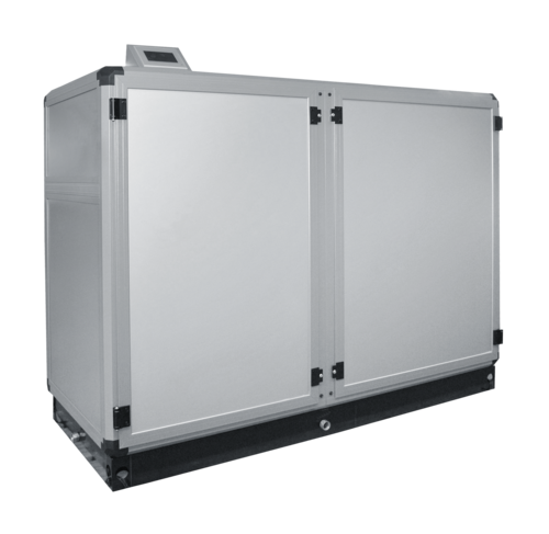
Compact duct device
At a Glance
Description
Technical data
Configuration
Planning and assembly instructions
- Duct device for the installation in the technical room - No disruptive devices in the swimming pool
- 2 sizes from 1250 to 2000 m³/h
- Different air routing variants permitting a simple duct routing
- Thermally decoupled housing
- Extensive functional and equipment features
- Good indoor climate in the pool thanks to constant admixture of outside air
- Simple heating connection through compact control station
- Broad range of accessories
- Coordinated air duct system
- Constant power adjustment by means of energy-saving, stepless EC direct current motors
- Additional savings and noise reduction through demand-dependent, stepless operation
- Better efficiency of energy recovery with reduced air volume
- Comparison between The supply and exhaust air volume can be carried out very precisely (vacuum setting)
Touch panel control equipped with a colour display of 4.3 inch
- Simple menu-driven operation
- Integrated web server
- Logging of alarms and any system data (actual values etc.)
- Comprehensive software options through simple configuration
- Switching between useful and eco mode through the internal timer or remote control
- Outside temperature dependent humidity shift
- Min. and max. limitation of the supply air temperature
- Various bus interfaces
Equipment list
Supply air fan, extract air fan, mixed air chamber, PWW heating register, cross-flow heat exchanger and heat pump unit for energy recovery, condensate collecting tray, outside and extract air filter, and control cabinet equipped with a control unit
Housing
Stable, corrosion-resistant profile frame construction made of aluminium hollow chamber profiles, powder-coated. The profiles are thermally decoupled by means of integrated plastic webs, so that the heat transfer between the device chambers and the environment can be reduced to a minimum level. Cladding panels equipped with highly insulating Hydrotec foam core. Circumferential base.
Supply/extract air fan
equipped with energy-saving, stepless EC direct current motors.
Mixing chamber
as an outside air/circulating air mixing chamber with two louvre flaps opening in opposite directions.
Air heater
Pull-out heat exchanger for hot water operation.
Supply air/extract air filter
Slide-in frame equipped with a Z line filter. Filter cell with pleated filter medium, fully incinerable and metal-free.
Energy recovery
Plate heat exchanger for the heat recovery of the sensible and latent heat energy contained in the air flows.
Coated stainless steel condensate pan equipped with a side drainage connector.
Heat pump unit
Heat pump unit equipped with a fully hermetic rotary piston/scroll compressor, evaporator, epoxy resin-coated condenser; bypass flap, condensate pan with drain
Control cabinet and control unit
integrated in the device with all modules for all tasks in the fields of control and monitoring.
Control package equipped with a touch panel control UNICON C, a colour display of 4.3 inch, and integrated in the control console.
Various interfaces (Ethernet TCP/IP, CAN, OPC, RS484, RS232) enable the connection to building management as well as third-party systems. Thanks to the optionally integrated web server, the operation or data transfer can take place through the internet as well. Various software options.
| Size | 1 | 2 |
|---|---|---|
| Nominal volume flow m3/h | 1250 | 2000 |
| Dehumidification performance (according to the standard VDI 2089) kg/h | 7.6 | 12.6 |
| Dehumidification performance (with recirculation mode 30°C/60% RH) 1) kg/h | 3.7 (2.1 *)) | 6.5 (2.9 *)) |
| For water surface max. 1) m2 | 25 - 45 | 40 - 80 |
| Operating temperature limit °C | from +15 to +35 | |
| Input power KW | 1.8 | 2.3 |
| Voltage V | 400 | 400 |
| Type | WRPC-K-1 | WRPC-K-2 |
1) The exact calculation in accordance with the standard VDI 2089 is required
*) Low temperature variant
Device
2 sizes
8 design variants
Alternative equipment
- Low-temperature variant
- Connection piece for transition to ISO duct
- Connection piece (special size)
- Connection piece for transition to round duct
- Low-temperature PWW heating register
- Conversion for the external installation of the control
- Duct humidity/temperature transmitter
- Duct humidity/temperature transmitter for rec. req.
Additional equipment
- Pool water condenser
- Height-adjustable feet
- Comfort humidity shift
- Room/water temperature deviation control
- Volume flow control equipped with pressure transmitter
- Electronic filter monitoring with display of the pressure
- Activation of useful/ECO operation
- Control of additional heating
- Activation of the fire damper
- Activation of the BMA/smoke detector with feedback
- Smoke detector with VDS approval including control
- Forced shutdown by the furnace
- Activation of fault message condensate pump
- External activation Switching contact "forced ventilation"
- Additional switching output "forced ventilation" with overrun
- Interface RS485 OSPA, OSF
- Interface Ethernet OPC protocol
- Universal I/O interface (0..10V) + DE / DA
- Interface Ethernet Modbus-TCP protocol V1.0
- Interface RS 485 Modbus-RTU protocol V1.0
- Web server with integration in UNICON C
- VPN remote maintenance router including Cloud portal
- Interface KNX/EIB
- Interface Ethernet Sopra Cloud Portal
- Interface Ethernet Modbus-TCP protocol V2.0
- Interface RS 485 Modbus-RTU protocol V2.0
Accessories
- Compact control station
- Mounting kit for the external control, with wall mounting
- Mounting kit for the external control, with flush mounting
- CAN bus cable 2x2x0.25 mm²
- Remote control W-FBS standard
- Replacement filter (set)
General planning information
- Determination of the size (according to VDI 2089)
- Determination of the space requirements and of the appropriate installation site
- Check of the size of the insertion opening
- Provision of electrical feed to the device
- Provision of electrical cables from the device to the outside temperature sensor
- Electric cable from the device to the room humidity/temperature transmitter (not applicable to the option "Duct humidity/temperature transmitter")
- If necessary, provide electrical cables from the device to options and accessories
- Provision of a (flow and return) heating connection pipe to the device
- Provision of a condensate line from the device to the sewer
- Determination of the number, length, type and position of the supply air floor slot rails
- Determination of the line routing and dimensions for the supply air duct
- Determination of the number, size and position of the exhaust air grilles
- Determination of the line routing and dimensions for the exhaust air duct
- Determination of the position and size of the outside air opening
- Determination of the routing and dimensions for the outside air duct
- Determination of the position and size of the exhaust air opening
- Determination of the line routing and size of the exhaust air duct